
I got tired of eveyone saying it's impossible so here you go:
![Image]()
I've not given a super in depth testing, just riding around the block at different throttle settings and RPM ranges. EFI light didn't turn on, also checked the voltages sent to the ECU and they look good.
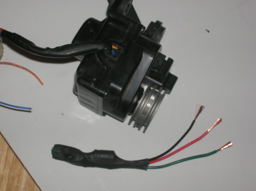
Here is what happens: The red and blue wires are connected to the motor and switch poles to move the exhaust valve. The feedback is a potentiometer, the green wire is ground and the yellow/red is +5V. The brown wire is the input to the ECU.
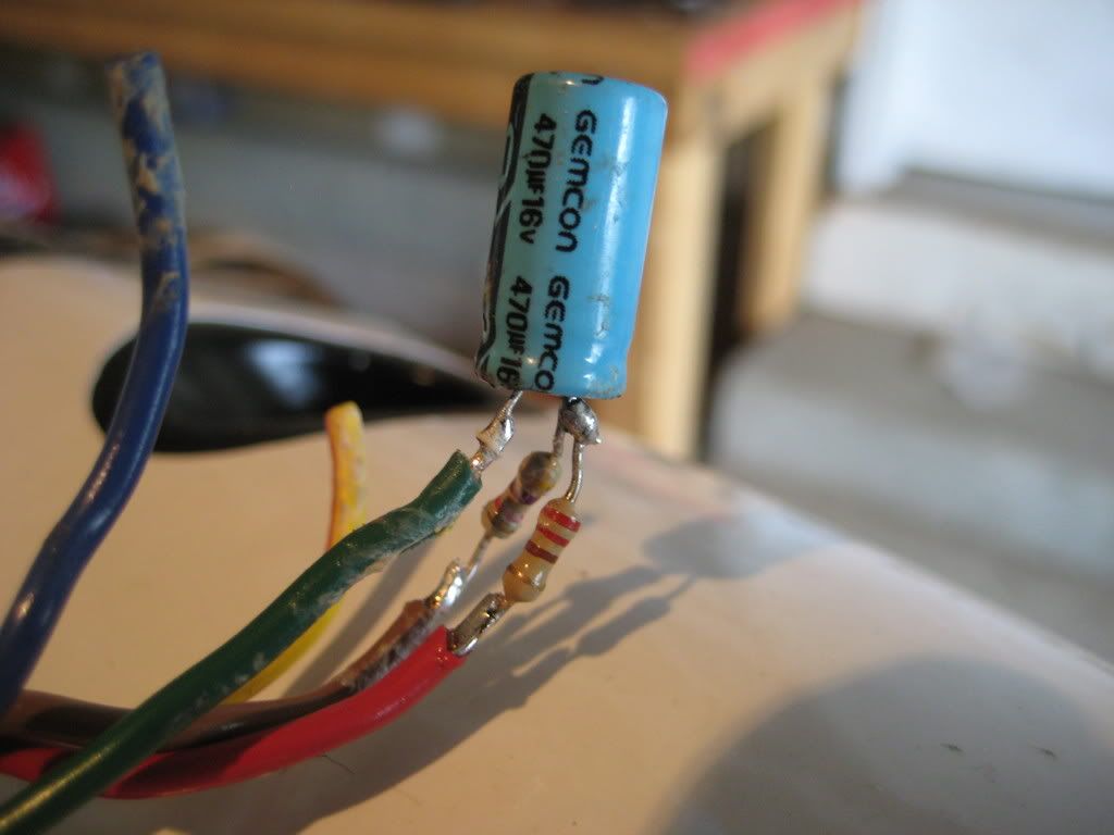
When the red wire is energized the motor spins in the direction that increases voltage to the signal (brown) wire. Therefore I set the red wire to charge the capacitor (220ohm resistor there to limit how fast it chargesit, could overshoot without it). If it needs to move the valve the opposite way the red wire goes to ground and will lower the voltage in the capacitor. This replicates the pot moving the opposite direction. The 4.7k ohm resistor is simply there to protect the input line incase you hook things up wrong and send 12V into it.
These are the components I had sitting around and can be varied. These are all common values for these components however.
Enjoy.

I've not given a super in depth testing, just riding around the block at different throttle settings and RPM ranges. EFI light didn't turn on, also checked the voltages sent to the ECU and they look good.
Here is what happens: The red and blue wires are connected to the motor and switch poles to move the exhaust valve. The feedback is a potentiometer, the green wire is ground and the yellow/red is +5V. The brown wire is the input to the ECU.
When the red wire is energized the motor spins in the direction that increases voltage to the signal (brown) wire. Therefore I set the red wire to charge the capacitor (220ohm resistor there to limit how fast it chargesit, could overshoot without it). If it needs to move the valve the opposite way the red wire goes to ground and will lower the voltage in the capacitor. This replicates the pot moving the opposite direction. The 4.7k ohm resistor is simply there to protect the input line incase you hook things up wrong and send 12V into it.
These are the components I had sitting around and can be varied. These are all common values for these components however.
Enjoy.
")