My cams dont line up when the t-mark is line up. The intake line is down and the exhust line is above with the head. I installed a degree will and the TDC is 4deg after tdc when i linw the t-mark. T-mark is tdc. Know what?
If I line g and h at the crank like in the picture the lines at the cams will not line up even with the head. I have the manual and have checked this many times. The lines are off. The bike runs good had never taking it apart.
The intake and exhaust marks on the cams are 4 degrees after TOP DEAD CENTER when the marks finaly line with the head. I took tha chain off to see if I could re line the marks with the crank. they will not line up. the srpockets are interchangeable.
this is going to help my wallet out a bunch when I decide to actually make time to do this it is probably way over due for my bike hopefully I'm not messing anything up too bad by holding off on doing >_<;
FYI, you do not have to remove the throttle bodies as described in the manual and this how-to. You can remove the cylinder head cover by loosening the throttle cables lock nuts to give it enough slack to remove the head cover.
Copy/paste from http://cbrworld.net/forums/thread/248256.aspx
This is a step-by-step tutorial to check the valve clearances on a 600RR (but much of it is applicable to most CBRs, please consult your service manual for the differences with your bike). It is recommended that valves be checked every 16k miles and adjusted if the valves are out of spec. Things you'll need:
standard hand tools
feeler gauges
First remove all fairings such that you have access to the engine. In this case, this required the removal of the lower and middle side fairings, upper (not pictured), air duct covers, and tank cover. Though not pictured here, I also disconnected the radiator from its mounting points (all hoses were still connected) to allow for some maneuverability later.
Remove the forward-most tank bolts. Pivot the tank back and suspend the tank. Here a small bungee cord is used to suspend the tank.
Remove ECM (Engine Control Module).
Disconnect the black 2P PAIR solenoid valve connector and starter switch connector(A), IAT sensor connector (B), and the air cleaner cover. Note: the starter switch connector here is shown as red because I use an RC-51 starter switch with my quick turn throttle.
Disconnect secondary air injector connectors and remove secondary air injectors.
Remove air filter and upper air cleaner housing.
Remove velocity stacks (C) and disconnect MAP sensor connector (D), vacuum hose to the MAP sensor connector, all hoses connected to the lower air cleaner housing, and lower air cleaner housing.
Remove the heat guard rubber and throttle bodies. After the throttle bodies are removed, then disconnect the throttle cables from the throttle bodies. Note: I have removed the PAIR valve so this pic may look different than your bike. If your bike has the PAIR valve, then remove it now.
Disconnect the ignition coil connectors and remove the ignition coils (E).
Remove the cylinder head cover bolts (circled below), the washers beneath them, and the cylinder head cover. Between the cylinder head cover and the engine casing beneath it is a thick rubber gasket. This gasket should come off with the cylinder head cover as its also seals the ignition coils on the cylinder head cover too.
Remove the timing hole cap and the o-ring beneath it.
Turn the CKP (crankshaft position) sensor rotor (F) such that the "T" mark (G) is aligned with the index mark (H) on the crankcase.
When the CKP is in this position, the index line on the CKP (I in the above pic) will line up with a "notch" inside the crankcase (J). This notch is not visible when looking at the timing hole head-on. We will make use of this notch soon.
This will place timing marks, IN and EX, on the cam sprockets flush with the cylinder head casing surface. The timing marks should be facing outward (as pictured below). If they are facing inward, then turn the CKP 360 degrees (i.e. 1 full turn).
Measure the valve clearances for the #1 (K) and #3 (L) intake valves with a feeler gauge.
Rotate the CKP 180 degrees such that the index line (I) is, as the service manual says, facing "up". This description in the manual is rather ambiguous. So use the "notch" (J) as the reference for the index line. You want the index line to be in line with the "notch" but on the other side of the CKP.
Measure the valve clearances for the #2 (M) and #4 (N) exhaust valves with a feeler gauge.
Rotate the CKP 180 degrees. This will again bring the "T" mark (G) in line with the index mark on the crankcase (H) but the timing marks on the cam sprockets will NOT be in line with the cylinder head casing surface. Measure the valve clearances for the #2 (O) and #4 (P) intake valves.
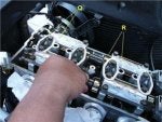
Rotate the CKP 180 degrees. This will again bring the index line (I) facing "up". Measure the valve clearances for the #1 (Q) and #3 (R) exhaust valves.
Turn the CKP (crankshaft position) sensor rotor (F) such that the "T" mark (G) is aligned with the index mark (H) on the crankcase.
When the CKP is in this position, the index line on the CKP (I in the above pic) will line up with a "notch" inside the crankcase (J). This notch is not visible when looking at the timing hole head-on. We will make use of this notch soon.
This will place timing marks, IN and EX, on the cam sprockets flush with the cylinder head casing surface. The timing marks should be facing outward (as pictured below). If they are facing inward, then turn the CKP 360 degrees (i.e. 1 full turn).
During this step in alignment of the markings: I presume it is more important to get the In/Ex markings flush with the casing as opposed to the T-mark dead on with the index notch correct? Mine seem to be a little off, when aligning the T mark the In/Ex markings are not parallel to the surface of the casing. When I make those parallel with the casing the T-mark is not in line with the index notch... So which is it?
Thx!
Related Threads
?
?
?
?
?
?
?
?
?
?
?
?
?
?
?
?
?
?
?
?
Honda CBR 600RR Forum
posts
3.9M
members
96K
Since
2003
A forum community dedicated to Honda CBR 600RR owners and enthusiasts. Come join the discussion about performance, engine modifications, troubleshooting, exhaust kits, and more!


")