

Hi all,
Intro
Now I found a couple of threads on this, but they were a couple of years old and I wasn't much of a fan of the method they used, one was using the un-rectified output of the alternator to switch a relay, and another was a timer based solution.
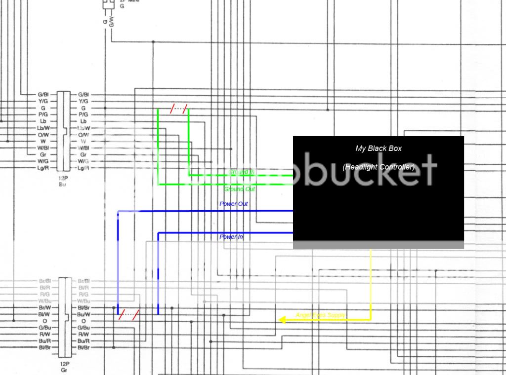
My controller monitors the battery voltage to decide if the headlights should be on or not.
What I have based my design on is the fact that before the bike starts you have at most 12.5V in the system and once your running and charging the battery you have around 14V.
The aim is that by monitoring the battery voltage, when the circuit senses the voltage getting above a threshold value the headlights turn on, and then stay that way.
Parts List
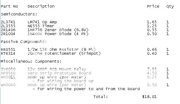
Here is a parts list of what you will need to build this controller with prices in $AU (and part numbers for jaycar)
![Image]()
To this you will have to add the cost of whatever you choose to protect your circuit with, for mine I have chosen to pot it to ensure a completely watertight seal, cost of around $3 for the box and around $35 for the potting compound - but I had way to much of that!
Power Consumption
The circuit in its standby condition only draws around 45mA, so is a hell of a lot more efficent than the headlights, once triggered it draws around 300mA, but that will change dramaticly depending on what relay you choose to use.
Basic Functional Description:
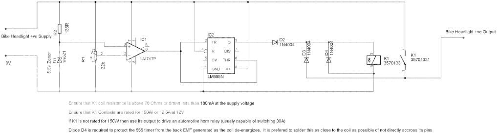
The schematic of the circuit you will be building:
![Image]()
The description:
Reference Voltage
R2 and the zener set up a reference point well below the minimum voltage the bike will operate under any normal circumstance (6.8V). The value of R2 is set to limit the current through the zener to just above its minimum current to allow it to operate at the correct voltage. In this case around 38mA
Voltage Sensing
R1 is a 20k potentiometer set to give an output at the wiper of around 6.3V with the bike off and around 7.3 with the bike running.
Comparator
IC1 is set up as a comparator with no feedback (open loop) to allow the output to swing between rails. The output will swing from around 10V to around 2V when the voltage at the -ve input goes above the reference (ie once the bike starts)
Inverter
IC2 is a 555 timer set up as an inverter. When you start the bike and cause the output of IC1 to swing to 2V this will cause the output of IC2 to go from 0V up to 12V applying power to K1 via D2.
The reason for doing this instead of simply swapping the inputs to IC1 is that the 555 can sink and source up to 200mA at its output compared to 20mA for the comparator (IC1), and due to the output of the comparator only swinging between roughly 2V and 10V I found it a lot simpler than setting up a transistor to allow full rail voltage swing (0V - 12V)
The Output
Once 12V is applied to K1 via D2 its contacts will make causing 12V to be applied via D3 latching the relay on regardless of what the voltage on the output of IC2 is. D2 is required to prevent the current being supplied via D3 from flowing into the output of IC2 when K1 is latched and IC2's output goes low. D3 is required to prevent the current being supplied via D2 from trying to drive the load (your lights) thereby exceeding the rated output current of IC2 and possibly pulling its voltage below what is required to activate K1.
Resetting the Controller
Finally the controller will reset when power is removed ie:
When you turn the key off, or;
When you stop the bike with the kill switch and then hit the starter (with the kill switch still in the stop position).
Building the Controller
To build it you will need everything on the parts list, some things may be substituted, or different values used, and feel free to ask if your not sure about something.
First step is to print off the schematic diagram, after that you just follow it and hook everything up as it says. You will need to cut the tracks on the bottom of the vero board to ensure everything is hooked up right, and there is plenty of info out there on the net about soldering and the like so I wont go into that here.
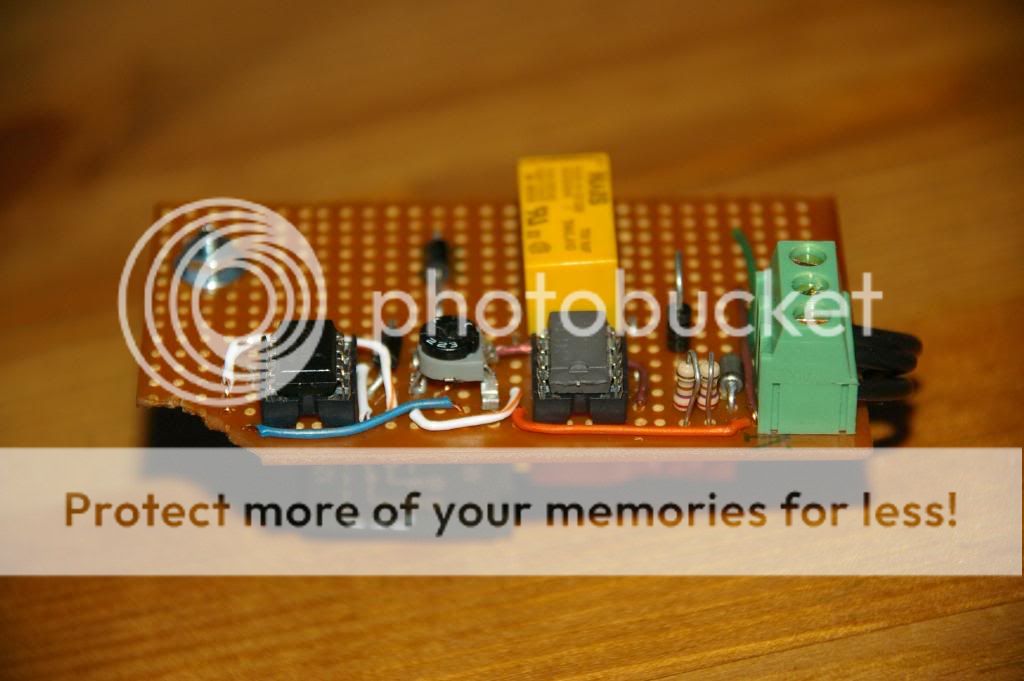
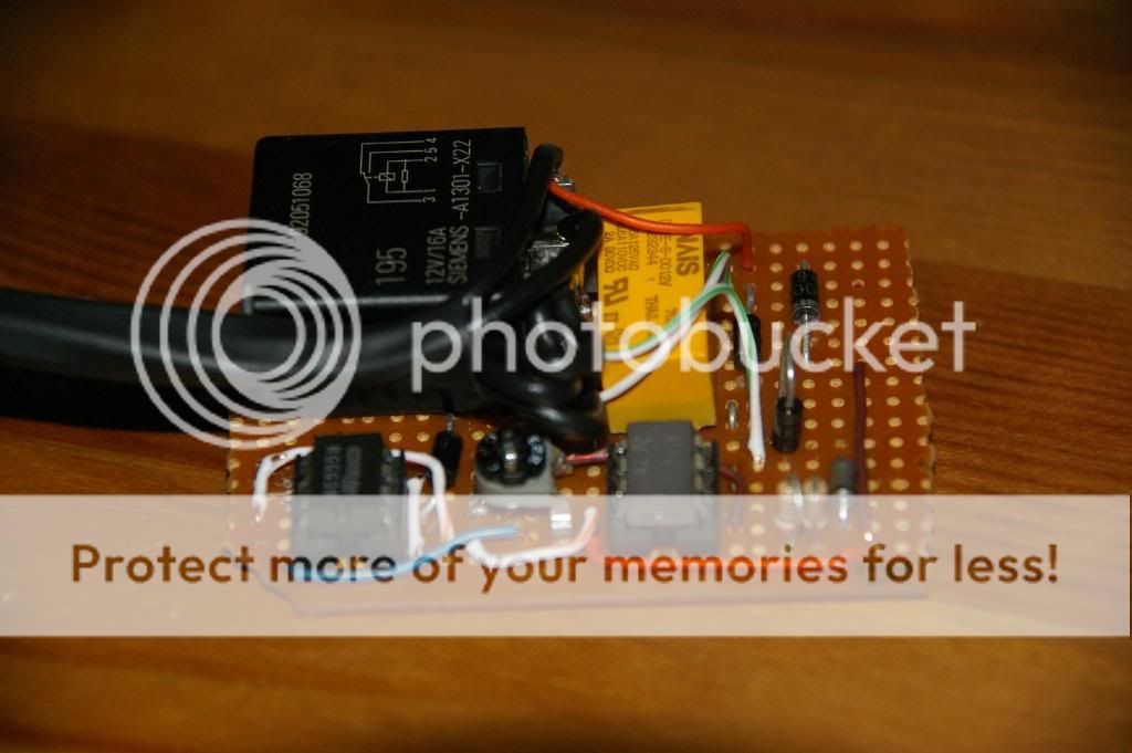
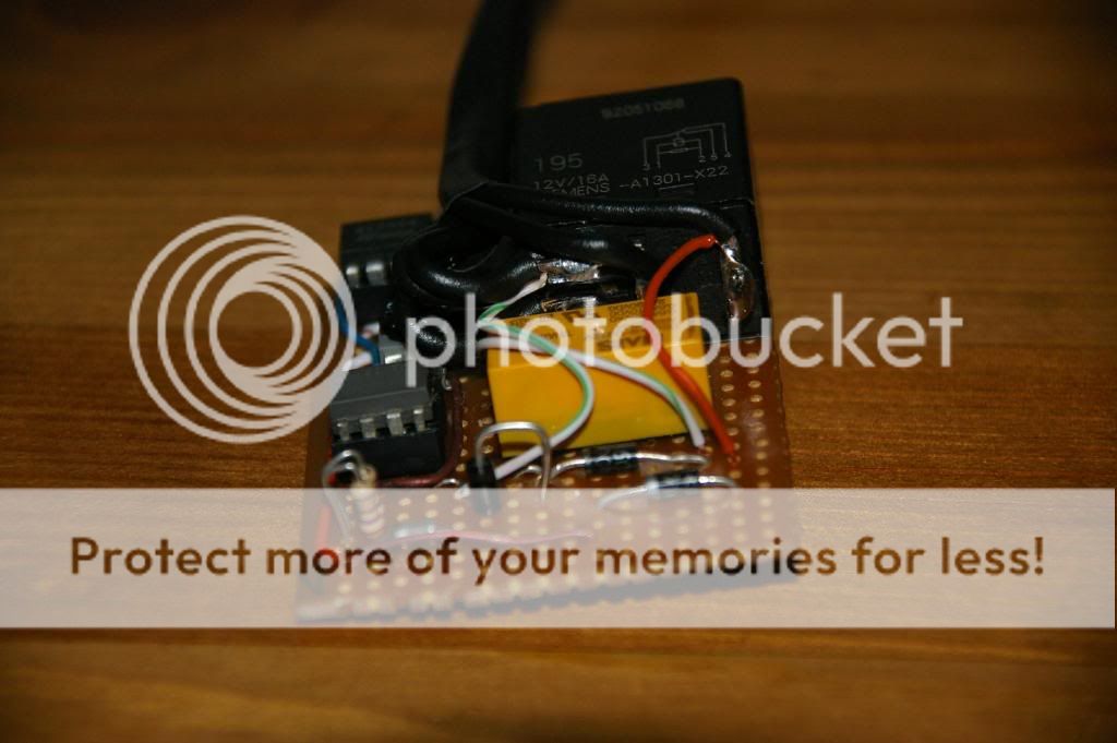
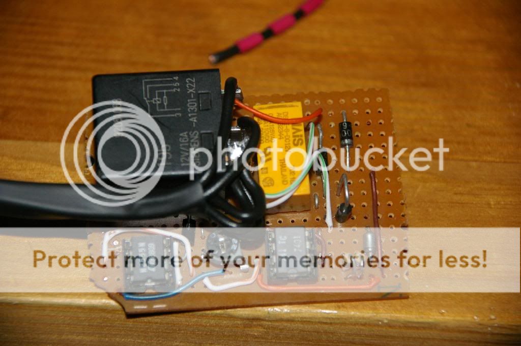
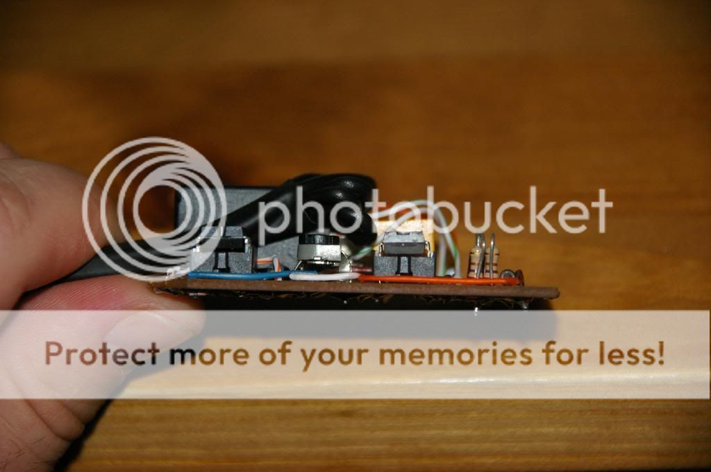
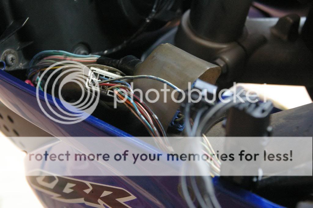
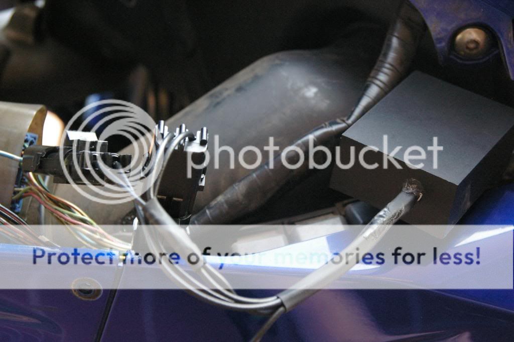
Some pictures of the finished circuit:
The last ones are of the enclosure I used and the potting compound.
![Image]()
![Image]()
![Image]()
![Image]()
![Image]()
![Image]()
![Image]()
![Image]()
To Be continued in the next post...
Nico
Intro
Now I found a couple of threads on this, but they were a couple of years old and I wasn't much of a fan of the method they used, one was using the un-rectified output of the alternator to switch a relay, and another was a timer based solution.
My controller monitors the battery voltage to decide if the headlights should be on or not.
What I have based my design on is the fact that before the bike starts you have at most 12.5V in the system and once your running and charging the battery you have around 14V.
The aim is that by monitoring the battery voltage, when the circuit senses the voltage getting above a threshold value the headlights turn on, and then stay that way.
Parts List
Here is a parts list of what you will need to build this controller with prices in $AU (and part numbers for jaycar)
To this you will have to add the cost of whatever you choose to protect your circuit with, for mine I have chosen to pot it to ensure a completely watertight seal, cost of around $3 for the box and around $35 for the potting compound - but I had way to much of that!
Power Consumption
The circuit in its standby condition only draws around 45mA, so is a hell of a lot more efficent than the headlights, once triggered it draws around 300mA, but that will change dramaticly depending on what relay you choose to use.
Basic Functional Description:
The schematic of the circuit you will be building:
The description:
Reference Voltage
R2 and the zener set up a reference point well below the minimum voltage the bike will operate under any normal circumstance (6.8V). The value of R2 is set to limit the current through the zener to just above its minimum current to allow it to operate at the correct voltage. In this case around 38mA
Voltage Sensing
R1 is a 20k potentiometer set to give an output at the wiper of around 6.3V with the bike off and around 7.3 with the bike running.
Comparator
IC1 is set up as a comparator with no feedback (open loop) to allow the output to swing between rails. The output will swing from around 10V to around 2V when the voltage at the -ve input goes above the reference (ie once the bike starts)
Inverter
IC2 is a 555 timer set up as an inverter. When you start the bike and cause the output of IC1 to swing to 2V this will cause the output of IC2 to go from 0V up to 12V applying power to K1 via D2.
The reason for doing this instead of simply swapping the inputs to IC1 is that the 555 can sink and source up to 200mA at its output compared to 20mA for the comparator (IC1), and due to the output of the comparator only swinging between roughly 2V and 10V I found it a lot simpler than setting up a transistor to allow full rail voltage swing (0V - 12V)
The Output
Once 12V is applied to K1 via D2 its contacts will make causing 12V to be applied via D3 latching the relay on regardless of what the voltage on the output of IC2 is. D2 is required to prevent the current being supplied via D3 from flowing into the output of IC2 when K1 is latched and IC2's output goes low. D3 is required to prevent the current being supplied via D2 from trying to drive the load (your lights) thereby exceeding the rated output current of IC2 and possibly pulling its voltage below what is required to activate K1.
Resetting the Controller
Finally the controller will reset when power is removed ie:
When you turn the key off, or;
When you stop the bike with the kill switch and then hit the starter (with the kill switch still in the stop position).
Building the Controller
To build it you will need everything on the parts list, some things may be substituted, or different values used, and feel free to ask if your not sure about something.
First step is to print off the schematic diagram, after that you just follow it and hook everything up as it says. You will need to cut the tracks on the bottom of the vero board to ensure everything is hooked up right, and there is plenty of info out there on the net about soldering and the like so I wont go into that here.
Some pictures of the finished circuit:
The last ones are of the enclosure I used and the potting compound.


To Be continued in the next post...
Nico


")